E. Detailing
1. Purpose
The process of detailing drawings ensure clarity, accuracy, and effective communication between customers and Seacoast. The final customer approved drawings provide precise specifications for manufacturing, validate designs before production, and serve as assembly instructions. These drawings also ensure compliance with industry standards and contract documents. As a quality record, they help maintain consistency and quality in the fabrication process. Customers receive the specified product that meets contract requirements, fabrication staff understand production requirements, and field crews can efficiently complete installations.
2. Definitions
For readability, this section uses the following definitions and abbreviations.
| Term | Definition |
|---|---|
| BOM | Bill of Material |
| EOR | Engineer of Record (EOR) is the owner's representative for design. |
| LOT | Letter of Transmittal (LOT) is a coversheet and communication package containing one or many submittals requiring customer approval or notification. LOTs are uniquely labeled using the format XXX-LOT-###, where XXX is the job number, and ### is a sequential three-position number. |
| NCR | Non Conformance Report (NCR) is a specific type of submittal that requires customer approval or notification. NCRs are uniquely labeled using the format NCR-###, where ### is a sequential three-position number. |
| QAI | The Quality Assurance Inspector (QAI) is the customer's representative responsible for commercial inspection. |
| QCI | Quality Control Inspector is the Seacoast staff responsible for the final inspection of fabrications and reports to the Quality Control Manager. |
| QCM | The Seacoast Quality Control Manual. |
| RFI | Request for Information (RFI) is a specific submittal that requires customer approval or notification. RFIs are uniquely labeled using the format RFI-###, where ### is a sequential three-position number. |
| RFM | Request for Modification (RFM) is a specific type of submittal that requires customer approval or notification. RFMs are uniquely labeled using the format RFM-###, where ### is a sequential three-position number. |
| SUB | Submittal (SUB) is communication that requires customer approval or notification. SUBs are uniquely labeled using the format SUB-###, where ### is a sequential three-position number. |
3. References
- 3.1 AISC Code of Standard Practice
- 3.2 Selected ASTM Standards for Structural Steel Fabrication
- 3.3 AASHTO Guide Specifications for Analysis and Identification of Fracture Critical Members and System Redundant Members
- 3.4 Single Point Lesson, SPL-014 Producing Burn Table Cut Files
- 3.5 Single Point Lesson, SPL-015 Bolt Length Tolerances
4. Responsibilities
- 4.1 Engineering Manager: Responsible for ensuring the accuracy of this procedure and that responsible staff follows the requirements in this section.
- 4.2 Customer: Responsible for approving shop and erection drawings that meet contract requirements.
- 4.3 Detailer: Responsible for following the procedures in this section when detailing drawings later approved by the customer.
- 4.4 Checker: Responsible for following the procedures in this section when checking drawings. The Detailer and Checker cannot be the same person.
- 4.5 Document Control: A functional responsibility typically belongs to the assigned Detailer or the Shop Engineer.
5. Quality Records
Unless otherwise noted, all Quality Records follow the Seacoast "Policy for Maintenance of Quality Records" documented in the QCM Quality Control Plan (Section A-page 13)
- 5.1 Approved Drawings: After approval, drawings are "Released for Construction." The master copy is stored on the server: [Job Folder] \Transmittals_RFI_RFM_Submittals\Shop Released\ CURRENT RELEASED FOR CONSTRUCTION SET
- 5.2 Contract Documents: Contract documents include the approved contract, design drawings, as-built drawings, project specifications, and addendum stored on the server: [Job Folder]\Project Documents
- 5.3 Letter of Transmittal (LOT): Document transmittal sent and received on the Transmittal log. Store both the issuance and response on the server: [Job Folder] \Transmittals_RFI_RFM_Submittals\Transmittals
- 5.4 Non Conformance Report (NCR): NCRs are a specific type of submittal. Store both the transmittal and response on the server: [Job Folder] \Transmittals_RFI_RFM_Submittals\NCR\
- 5.5 Request for Information (RFI): RFIs are a specific type of submittal. Store both the transmittal and response on the server: [Job Folder] \Transmittals_RFI_RFM_Submittals\RFI\
- 5.6 Request for Modification (RFM): RFMs are a specific type of submittal. Store both the transmittal and response on the server: [Job Folder] \Transmittals_RFI_RFM_Submittals\RFM\
- 5.7 Submittals (SUB): Submittals require a customer's approval or notification. Store both the submittal and response on the server: [Job Folder] \Transmittals_RFI_RFM_Submittals\Submittals\
6. Procedure
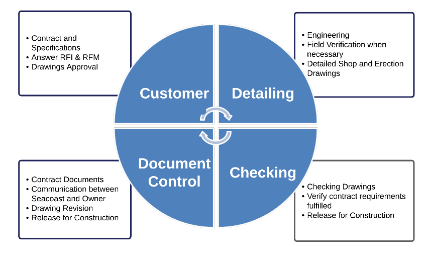
Figure E-1. Detailing Process Overview
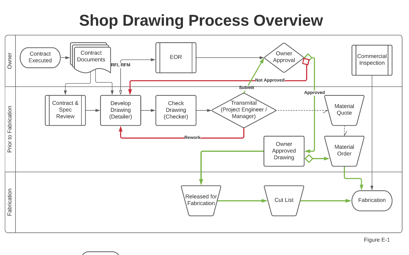
Figure E-2. Shop Drawing Process — Contract to Fabrication
6.1 Detailing Standards
Seacoast developed a detailing standard describing technical preferences and requirements when detailing. The standard shows special information required on advance bills of Material, such as allowances for cuts, camber, or supplementary requirements. The detailing standards include how bills of Material are prepared, which, at a minimum, include:
- 6.1.1 Sizes and quantities.
- 6.1.2 Appropriate specification references.
- 6.1.3 Special ordering information.
- 6.1.4 Any allowances or tolerances. This is typically on part dimension or the tolerance block (lower-left) and not specifically on the BOM block (upper-right block).
- 6.1.5 How to present fracture critical material
The detailing standards describe Seacoast's methods of drawing layout, including, but not limited to:
- 6.1.6 Sections and views.
- 6.1.7 Title block information.
- 6.1.8 The method of designating shipping sequences.
- 6.1.9 The Piece marking system.
- 6.1.10 Commonly used shop abbreviations.
- 6.1.11 Showing bolt placement lists (including bolt type and installation requirements).
- 6.1.12 Information required on weld symbols, including any special NDT requirements.
- 6.1.13 The detailing standards describe the method for:
- 6.1.13.1 Selection of connection type, connection geometry, and connection material.
- 6.1.13.2 Detailing holes, fasteners, washers, cuts, and copes.
- 6.1.13.3 Assignment of appropriate and complete welding symbols (shop and field welds).
- 6.1.13.4 Select bolt installation method (for shop-installed bolts).
- 6.1.13.5 Showing surface preparation (including specification of surface finish).
- 6.1.13.6 Designating coating requirements (including masking, coating materials, and dry film thickness).
- 6.1.13.7 Showing any necessary special instructions to fabricate and erect the steel.
- 6.1.14 How to present fracture critical material and welds to the shop and field
- 6.1.15 How to present information on shop assembly (blocking) drawings
Seacoast standard detail set (Figure E-3) ensures shop fabrication and erection drawings meet contract requirements, AISC standards, industry standards, and the requirements of Seacoast, Inc.
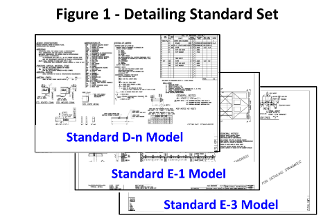
Figure E-3. Detailing Standard Set
Table E-1. Standard Models
| Standard | Overview |
|---|---|
| D-n Model | Detailing standards Bill of Material Revision Control Process Commonly used shop abbreviations Additional requirements |
| E-1 Model | Example of a top-level Erection Drawing |
| E-3 Model | Example of additional detailed sections referred to in model E-1, showing an installation progression |
6.2 Digital Document Production
Seacoast detailers typically use AutoCAD or SolidWorks for producing fabrication and erection drawings for customer approval. Once approved, Seacoast uses the digital drawing files to create part files for computer-controlled fabrication equipment.
When using AutoCAD software for producing drawings:
- 6.2.1 Set the SCALE to 1 to 1
- 6.2.2 Use AutoCAD double-precision data
- 6.2.3 Use the following standard layers:
- 6.2.3.1 Cut for part dimensions
- 6.2.3.2 Center Mark, for center marking hole locations
- 6.2.3.3 Existing (optional) for existing field reference points
- 6.2.3.4 Misc (optional), as necessary
- 6.2.4 Hand-type dimensions, when practical
- 6.2.5 Pull dimension lines orthogonally to eliminate skew
After customer approval, create the part files for burn table nesting and cutting. Create a single file for each part being burned.
- 6.2.6 Name the file "XXXX PM," where XXXX is the Seacoast Job Number and PM is the Piece Mark
- 6.2.7 Save the file to the Seacoast Server under
S:\Burntable\[Job File]\[XXXX PM.dwg]
When it is suspected that digital drawings are not accurate — due to unusual, excessive, or systematic incorrect dimensions identified during the checking process or fabrication non-conformances — inaccuracies are most often introduced unintentionally by:
- 6.2.8 Unintentional mistakes by snapping to the wrong object or clicking an intersection instead of an endpoint. These human errors can be subtle and hard to find on complex drawings.
- 6.2.9 Imported PDFs for object snaps and offsets will introduce some errors, given how PDFs store data.
- 6.2.10 Externally created geometry. Drawings made by external software might be single precision, whether as DWG files or in another imported format.
- 6.2.11 Pasting from the Windows clipboard is also only single precision.
If, after checking the above, it is suspected that AutoCAD software is inaccurate, confirm the software accuracy. Accuracy errors tend to spread and accumulate within a drawing. Methods for manually checking for inaccuracies:
| Method | Description |
|---|---|
| Reference geometry | Dedicate one or more layers to maintain a framework of reference geometry in a unique color. Use the carefully created reference geometry to make other objects and check your work. Typical reference objects are rectangles, closed polylines, lines, circles, and point objects. Use the 3-4-5 method to check the software's accuracy by creating a check print and checking it with a ruler. |
| User Coordinate System (UCS) | Ensure that the UCS coincides with the WCS, the ELEVATION command is set to 0, and the THICKNESS system variable is set to 0. |
| Annotation layers | Dimensions and leaders can get in the way visually and geometrically, so turning off their layers is advised. |
| Temporary hides | Use the HIDEOBJECTS command to suppress selected objects that get in the way of object snapping. Use the UNISOLATEDOBJECTS command to restore them quickly. |
| Direct measurement | Check locations and distances with the ID command for coordinates. The properties palette for selecting and displaying coordinate and length properties, and the DIST or MEASUREGEOM command for distances between objects. |
| Decimal places | Use the UNITS command to increase the number of decimal places displayed when using ID, DIST, MEASUREGEOM, and the Properties palette. |
| Precision dimension style | For comparing several objects, create a dimension style with the Primary Units precision set to 8 decimal places. Name it something like "Precision" and use it with the DIM command to spot-check distances and angles. |
| Non-zero coordinates | Sometimes geometry having non-zero Z coordinates in 2D drawings causes issues. Instead of using the FLATTEN command, use the QSELECT command to specify the object type. For line objects, set the Start Z < > 0 to see the extent of the problems and then correct them directly using the Properties palette without projection. Repeat the process for End Z < > 0 and other object types. |
6.3 Detailing
-
After reviewing the contract documents, Contract and Specification Review (S06 form), design plans, as-built plans, and specifications, if more information is needed:
- Request for Information (RFI) or Request for Modification (RFM): The Detailer follows the procedure for generating and documenting an RFI (or RFM) as in QCM Document, Data & Quality Record Control (Section D).
-
Detail a drawing that fulfills project requirements following Seacoast detailing standards.
-
When the drawing is ready to be checked, the Detailer ensures the "CHECKED BY" field in the title block is blank and provides the drawings to the assigned Checker.
-
See procedure "Checking." Note: a drawing may go through multiple iterations of detailing/checking before finalized
6.4 Checking
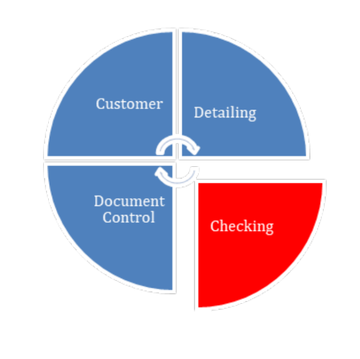
Figure E-4. Checking Phase
-
The Detailer provides the drawing to be checked
-
Checking includes comparing shop drawings, digital models, and erection framing drawings to project requirements that include at a minimum:
- Geometry
- Use of the correct connections
- Proper notes
- Proper material usage
- Assignment of complete welding symbols
- Proper coating and preparation
- A proper bill of materials matching drawing details
- Proper sequencing of fabrication progression
- Proper representation of erection framing drawings, including the notation of any necessary instructions and depiction of details essential to conduct the work in the field
- Consistency of labeling between drawing details, fabrication progression, and erection frame drawings
- Special purchasing data complies with contract documents
-
When checking is complete, the Checker will initial and date the original tracings in the appropriate location in the title block and return them to the Detailer
-
The Detailer will back check the items noted by the Checker for agreement
-
When no edits are necessary, the drawings are ready for submittal. See procedure Control of Approval Documents.
6.5 Control of Approval Documents
-
Once checking complete, submit drawings to the Customers Representative for Design (EOR) with a submittal cover sheet using a transmittal form. Detailed procedures are provided in QCM Document, Data & Quality Record Control (Section F).
- Log the transmittal on the job transmittal log
- Save a copy of the transmittal package to the server
-
When the Engineer of Record responds, initially document:
- Log the response on the job transmittal log
- Save a copy of the transmittal response to the server
-
Based on the EOR response, update the revision number on the drawing:
- Stamps Approved and makes comments: The revision number does not change. Approved (AN) Rev 0 becomes Rev 0AN
- Result in a substantial change, Material or quantity change, effects on installation, or modifications not agreed upon by Seacoast, Inc.: Put the drawing back through the checking process and resubmit the revised drawings with a sequential revision number. For example Rev 0 becomes Rev 1
- If Seacoast requires a change solely to clean up EOR comments, or facilitate ease of fabrication: The revision number does not change. Comment (C) Rev 5A becomes Rev 5C1 If there is more Number than one Comment sequentially 5C1, Revision 5C2, etc...
-
The Detailer shall capture all revisions called for by the engineer and place a triangle with the appropriate revision number inside it at each change noted and in the Revisions & Print Records next to the title block (Figure E-5, item 1).
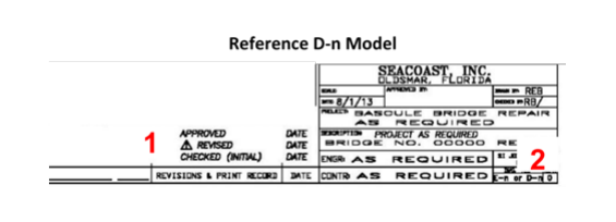
Figure E-5. Reference D-n Model — Revision Mark Locations
- Based on the EOR response [If the EOR [Then] response...] Resubmit Repeat the procedures for checking and resubmitting the drawings. Approved as noted repeat the checking process before issuing. Once checked, see the procedure Released for Construction drawings. Approved See procedure Released for Construction drawings.
6.6 Released for Construction
-
Print a clean copy of the approved drawing
-
Stamp the drawing "Released for Construction" (Figure E-6) and document:
- [By:] Initials of the issuer, usually the shop engineer
- [Date]: Date of issuance
- [Comm Insp]: if the owner is sending a QAI
- [Fab (Hours & Due)]: Fabrication hours to complete and when to complete it.
- [Mach (Hours & Due)]: Machining hours to complete and when to complete it.
- [Coat (Hours & Due)]: Shop painting hours and when to complete it.
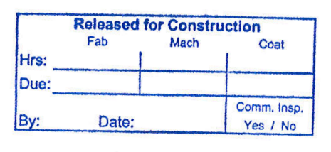
Figure E-6. Released for Construction Stamp
-
Update the CURRENT RELEASED FOR CONSTRUCTION SET pdf document to include the newly issued drawing. If it is replacing an earlier version, replace that version.
-
Make enough copies of the stamped drawing for distribution, typically Quality Control, Shop Management, Shop 1, Shop 2, and Purchasing. Additional documents for QAI or others are allowed.
-
On the copy, write to who it is issued.
-
Physical copies of the released for construction drawings are controlled documents and therefore tracked. Document drawing issuance on the transmittal log as a No Submit, No Transmit, shop communication only entry in the transmittal log.
-
Distribute the copy and collect and destroy any previous revisions. Before destroying the QC Copy Drawings, transfer any QCI inspection documentation to the new drawing.
6.7 Superseded Drawings
-
The Shop Engineer or Detailer will immediately notify the Shop Forman and have all copies of the affected drawings removed from the shop floor and any other copies in circulation and documented on the Transmittal log.
-
If a drawing has a superseded mark and particularly affected details cannot be isolated: The entire drawing is to be considered superseded -- no fabrication work should be performed or continued based on these drawings. Put the drawing back through the checking process and revise drawings with a sequential revision number.
- For example, Rev 0A becomes Rev 1AC with changes
- Place a triangle with the appropriate revision number inside it at each change noted
- Update the Revisions & Print Records next to the title block
Follow the procedure Released for Construction.
6.8 Subcontractor Qualification
Initial Qualification
Evaluate potential subcontractors before contracting with an outside firm.
Minimum Requirements
Seacoast requires that any subcontractor meet minimum requirements:
- Five years of experience in sizing connections
- Detailing and checking shop and erection drawings that meet industry standards and Seacoast requirements for various structures representative of projects the company provides.
- Training in courses with a written curriculum in steel design and connection design
- Evidence of representative work
Management of Subcontractors
If a company meets the requirements of this section, the Engineering Manager may approve them as a subcontractor. The contract for services is handled on a project-by-project basis. Seacoast retains final review and approval for contracted work and follows the same Control of Approval Document and Released for Construction procedures included in this section.
7. Revision History
| Revision Date | Approved By | Summary of Change |
|---|---|---|
| 2026-01-15 | Engineering Manager |