J. Bolt Installation
Revision History
| Revision Date | Approved By | Summary of Change |
|---|---|---|
| 2022-03-10 | Engineering Manager |
Purpose
To ensure consistent tension in the bolted assembly that produces the proper connection meeting the requirements of the RCSC Specification for Structural Joints Using High-Strength Bolts and contract requirements.
Definitions
- EOR: * Engineer of Record Faying Surface In a connection, the contact surface between two connected elements. Firm Contact The condition exists on a faying surface when the plies are solidly seated against each other but not necessarily in continuous contact. Grip The total thickness of material a bolt passes through, exclusive of washers or direct tension indicators. *High-strength An
- F3125: or
- F3148: bolt or bolts* an alternative design bolt meets the
- RCSC: Section 2.12. Inspector The person responsible for verifying that the contractor has satisfied the provisions of this section and contract requirements when performing the work. Joint The connection area in which one weld or group of bolting assemblies joins two or more members or connection elements. Lot A quantity of uniquely identified bolting components or assemblies or matched bolting assemblies of the same nominal size and length produced consecutively from a single mill heat of material and processed at one time, by the same process, in the same manner, so that statistical sampling is valid. Manufacturer The party that produces one or more bolting components Protected Storage is protected from Storage environmental conditions and contamination detrimental to installing high-strength bolts. Skidmore A calibrated Skidmore Wilhelm bolt tension calibrator is used to verify that the bolting assembly, pretensioning method, and tools can achieve the required tensions. Snug-Tight A condition where plies are in Condition firm contact and each bolting assembly has at least the tightness attained by a few impacts from an impact wrench, resistance to a non-impacting wrench, or the full effort of an ironworker using a spud wrench. Sufficient Having the end of the bolt Thread extending beyond or at least Engagement flush with the nut's outer face is a condition that develops the strength of the bolt. Touching up The process of re-tightening a bolt loosened by the tightening of adjacent bolts
References
The following references directly support this Section
-
RCSC Specification for Structural Joints Using High-Strength Bolts
-
ASTM F3125/F3125M Standard Specification for High Strength Structural Bolts, Supplementary Requirements and Annexes (ASTM F3125)
-
Various sections of the Seacoast Quality Control Manual (QCM) support the documentation within this Section
-
Seacoast Training for Bolt Installation
-
The contract required standards, specifications, and requirements
Responsibilities
- Quality Control Manager: Manager will ensure that the appropriate personnel follows the procedures. Shop or Field The Shop or Field Engineer is Engineer responsible for ensuring that assemblies' bolting follows this section's requirements. Competent Person Qualify a competent person by training following the requirements of this section. The qualified person is responsible for following this procedure when installing high-strength bolts in structural joints.
Quality Records
Unless otherwise noted, all Quality Records follow the Seacoast "Policy for Maintenance of Quality Records" documented in the QCM Quality Control Plan (Section A-page 13) 1. Rotational Capacity Testing Form for Long Bolts (RC-1): The field or shop engineer retains a physical copy of the form for the contract duration. In exception to the QR retention policy, destroy the document after the contract is complete. 2. Rotational Capacity Testing Form for Short Bolts (RC-2) 3. Daily Snug-Tight Testing (ST-1)
Procedure
Section Index
[RCSC]
[Additional requirements:] Take only as many bolting components and bolting assemblies as anticipated during the work shift from protected storage.
2.10.3
Return unused bolting assemblies to protected storage at the end of the work shift.
2.10.4
Bolting components (including some bolting assemblies) may be field lubricated to help installation as deemed practical or necessary[^3].
2.10.5
Heavy hex head bolting components for snug-tightened joints that accumulate rust or dirt shall not be incorporated into the work unless they are cleaned and lubricated.
2.10.6
Bolting components and bolting assemblies intended for pretensioned or slip-critical joints that accumulate rust or dirt shall not be incorporated into the work unless cleaned and lubricated and then retested following the pre-Installation verification procedure later in this section. See Section 2.10.4 above for prohibitions on relubrication.
2.10.7
Temporary bolts are exempt from this section's storage requirements
2.11
The reuse of bolts is allowed per RCSC as follows: 1. Allowed with Critical EOR approval: Pretensioned or Slip 2. Not Allowed: Any Type (Galvanized) Group 144 Bolt Assemblies Group 150 Heavy Hex Bolts
**[SC Faying
[Requirement] | 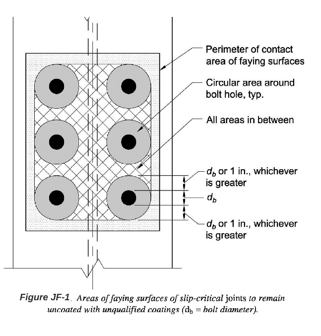
Uncoated
Shall be free of scale | (except tight mill scale), | coatings, and overspray in | areas closer than one bolt | diameter but not less than 1 | in. from the edge of any hole | and in all areas within the | bolt pattern (see Figure | JF-4). Otherwise, these | faying surfaces are blast | cleaned before assembly. *Class A or B
Follow the release for | construction drawings and | QCM - K Paint procedures. | Coated faying surfaces are | blast cleaned per contract | documents and subsequently | coated with a qualified | coating. Per the coating | manufacturer's application | instructions, do not assemble | the plies of slip-critical | joints with coated faying | surfaces before the coating | has fully cured. | Coatings that differ from Class A or Class B coating are permitted with EOR approval; consult the Shop, Field, or Engineering Manager when necessary. If approved, the faying surfaces shall be free of coating and overspray in areas closer than one bolt diameter but not less than 1 in. from the edge of any hole and in all areas within the bolt pattern (see Figure JF-1).
Galvanized[^6]
Galvanized faying surfaces are hot-dip galvanized per the requirements of ASTM A123. Power or hand wire brushing is not permitted. Galvanized faying surfaces are designated as Class A for design purposes.
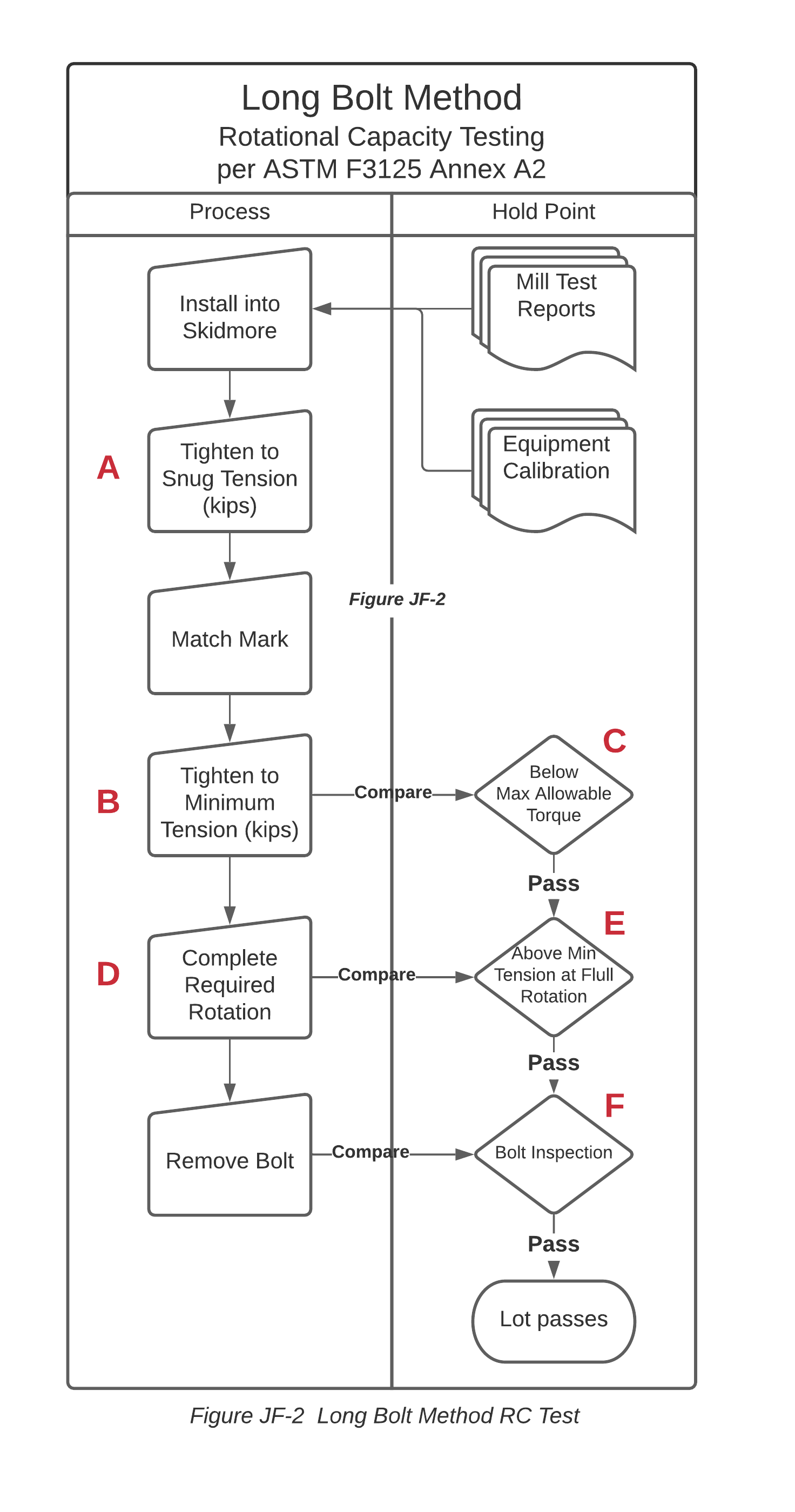
Figure J-1. [RCSC]
-
- +
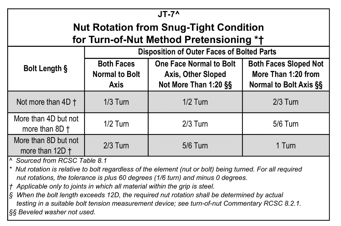
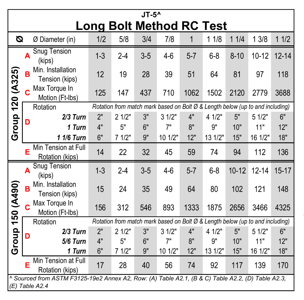
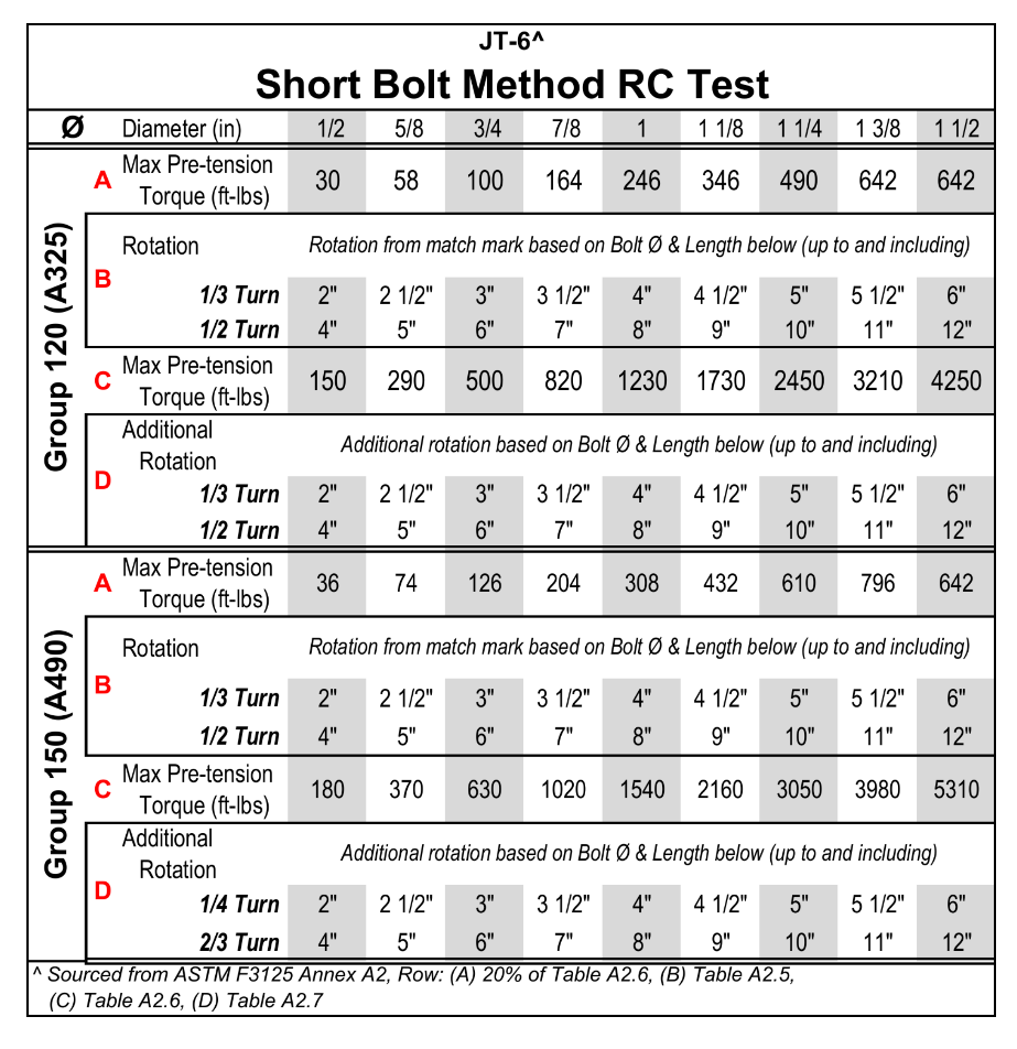
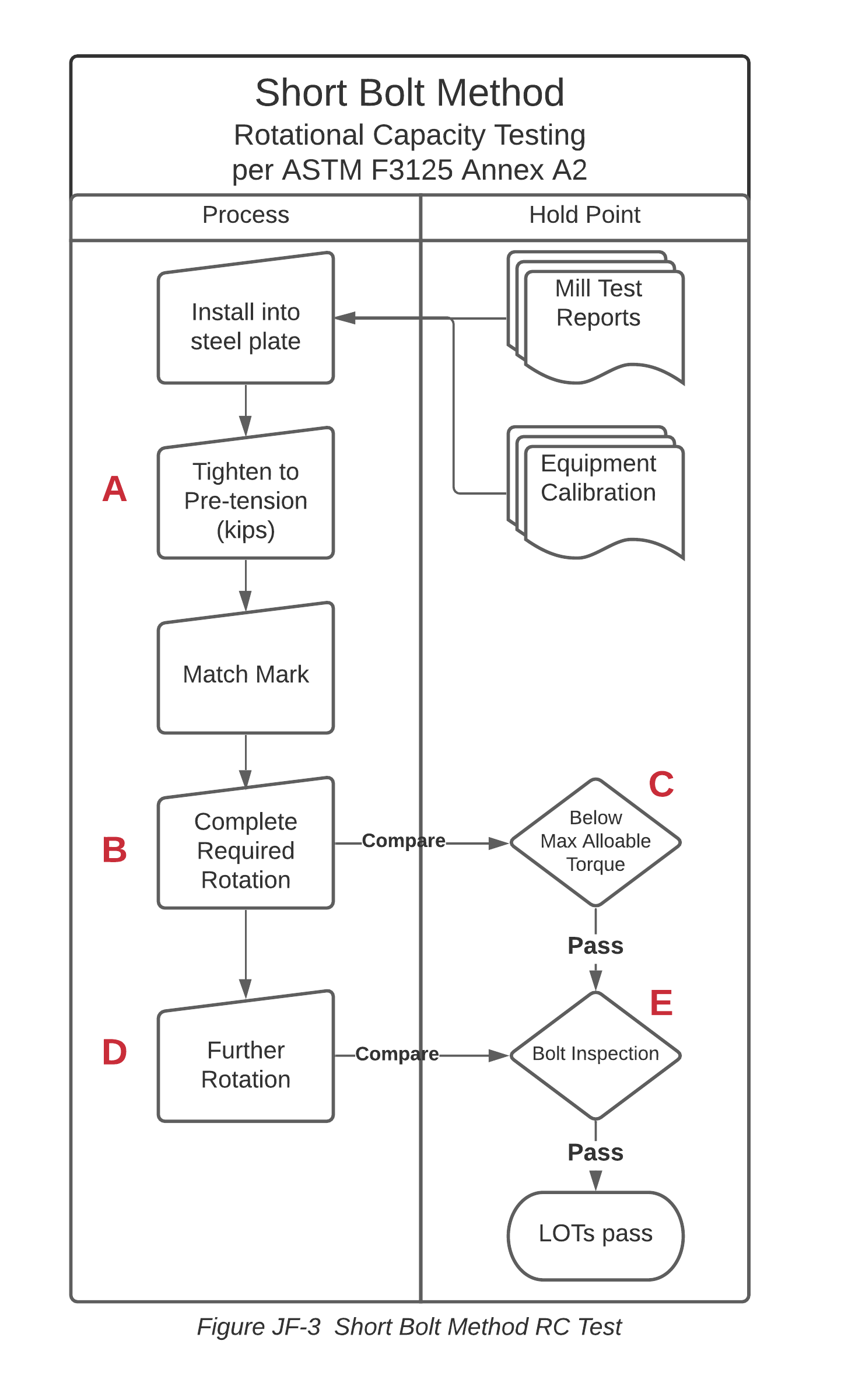 1 | Install the bolt and any | | required spacers in the steel plate so that the bolt stick-out is flush with the nut to a maximum of three threads stick-out, typically providing three to five threads within the grip. 2 | Pre-tension the assembly in | | the steel plate. Do not exceed 20% of the torque permitted, for convenience listed on row (A) of the table[^14]. 3 | Match-mark the bolt, nut, and | | plate as documented on form RC-2. 4 | Tighten the nut to the | | rotation identified in row (B) of the table while preventing the bolt head from rotating. Read the torque with the nut in motion. 5 | The torque measurement taken | | in step 4 should not exceed the values listed in row (C) of the table^2^. These torque values are based on the assumed tension of 1.15 × minimum installation tension. Therefore, assemblies that exceed the listed torque fail the test. 6 | Further tighten the bolt with | | the additional rotation identified in row (D) of the table. Assemblies that strip or fracture before this rotation fail the test. 7 | (E) Loosen and remove the | | nut. There shall be no signs of thread shear failure, stripping, or torsional failure. The nut shall turn on the bolt threads to their position during the test. The nut does not need to run past its position during the test. The inability to turn the nut by hand is considered a thread failure. Broken bolts fail the test. Elongation of the bolt in the threads between the nut and the bolt head is expected and [not considered a failure].
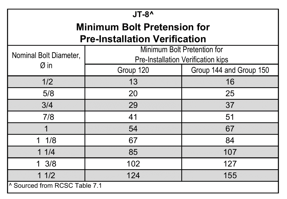
| 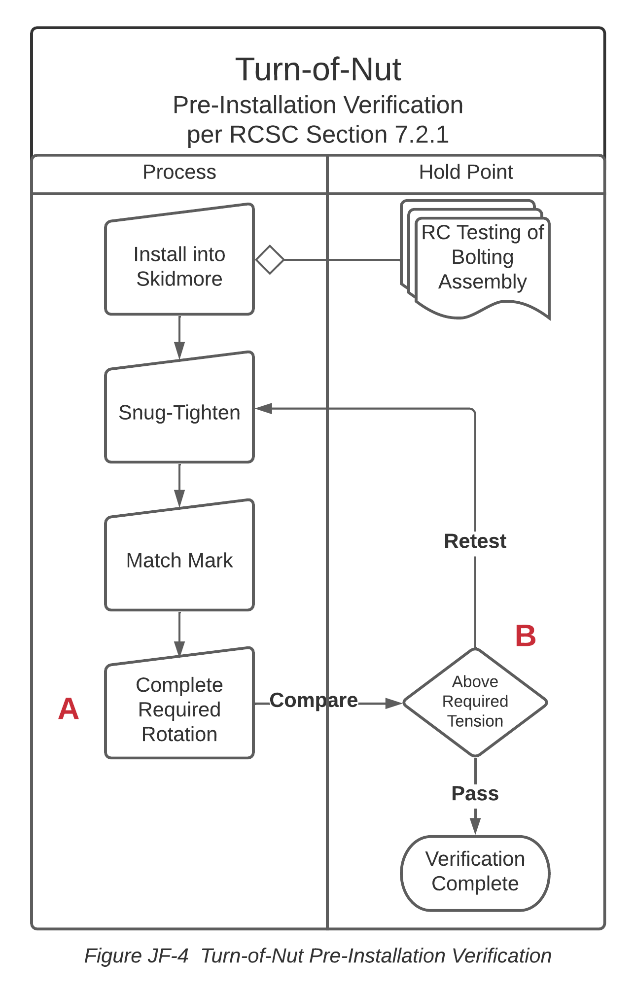 | 1 Install the bolt and any | | required spacers in the | | Skidmore so that the bolt | | stick-out is flush with the | | nut to a maximum of three | | threads stick-out, typically | | providing three to five | | threads within the grip. | | 2 Tighten the bolting assembly | | to a snug-tight condition in | | the Skidmore using the tools, | | bolting components, assembly | | configuration, and | | installation methods to be | | used in work. | | 3 Match-mark the bolt, nut, and | | faceplate of the Skidmore. | | Mark the faceplate of the | | Skidmore the amount of | | rotation identified in Table | | JT-7 (see Annex -- Testing | | References). | | 4 Tighten the nut to that | | rotation (A) | | Pre-Installation Verification. | | 5 If the actual pretension | | (B) for the bolt group | | developed in the bolting | | assembly is less than | | specified in Table JT-8 (see | | Annex -- Testing References), | | determine the cause(s) and | | resolve it before installing | | the bolting assemblies in | | work. It is permitted to | | clean, lubricate, and retest | | the bolting assemblies as long | | as all assemblies are treated | | equally. Verification is | | complete when each bolt meets | | or exceeds the tension | | specified in Table JT-8 |
1. 2 hole quality as required in section J-2. *The Inspector observes the contact surface and hole quality.: Verify the contact surface and
2. 3 to a snug-tight condition: - Align bolt holes to permit insertion of the bolts without undue damage to the threads; - Place bolt assemblies in all holes with washers positioned per construction drawings or contract documents and nuts threaded to complete the assembly; - Compact the joint, progressing systematically from the most rigid part of the joint. - Install the joint to the snug-tight condition with sufficient thread engagement[^17]. *The Inspector verifies through observation that snug-tight condition was achieved for all assemblies.: Install all bolting assemblies
3. 4 steel surface.: Match-mark the bolt, nut, and
| 1 Install the bolt and any | | required spacers in the | | Skidmore so that the bolt | | stick-out is flush with the | | nut to a maximum of three | | threads stick-out, typically | | providing three to five | | threads within the grip. | | 2 Tighten the bolting assembly | | to a snug-tight condition in | | the Skidmore using the tools, | | bolting components, assembly | | configuration, and | | installation methods to be | | used in work. | | 3 Match-mark the bolt, nut, and | | faceplate of the Skidmore. | | Mark the faceplate of the | | Skidmore the amount of | | rotation identified in Table | | JT-7 (see Annex -- Testing | | References). | | 4 Tighten the nut to that | | rotation (A) | | Pre-Installation Verification. | | 5 If the actual pretension | | (B) for the bolt group | | developed in the bolting | | assembly is less than | | specified in Table JT-8 (see | | Annex -- Testing References), | | determine the cause(s) and | | resolve it before installing | | the bolting assemblies in | | work. It is permitted to | | clean, lubricate, and retest | | the bolting assemblies as long | | as all assemblies are treated | | equally. Verification is | | complete when each bolt meets | | or exceeds the tension | | specified in Table JT-8 |
1. 2 hole quality as required in section J-2. *The Inspector observes the contact surface and hole quality.: Verify the contact surface and
2. 3 to a snug-tight condition: - Align bolt holes to permit insertion of the bolts without undue damage to the threads; - Place bolt assemblies in all holes with washers positioned per construction drawings or contract documents and nuts threaded to complete the assembly; - Compact the joint, progressing systematically from the most rigid part of the joint. - Install the joint to the snug-tight condition with sufficient thread engagement[^17]. *The Inspector verifies through observation that snug-tight condition was achieved for all assemblies.: Install all bolting assemblies
3. 4 steel surface.: Match-mark the bolt, nut, and
- 2 to the snug-tight condition: - Align bolt holes to permit insertion of the bolts without undue damage to the threads; - Place bolt assemblies in all holes with washers positioned per construction drawings or contract documents and nuts threaded to complete the assembly; - Compact the joint, progressing systematically from the most rigid part of the joint. - Install the joint to the snug-tight condition with sufficient thread engagement[^18]. The Inspector verifies through observation that snug-tight condition was achieved for all assemblies.: Install all bolting assemblies
***Rotational
***Turn of