T. Fracture Control Procedure
1. Purpose
To provide additional control for fabrication, inspection, and testing of non-redundant materials designated as Fracture Critical by the contract documents.
2. Definitions
For readability, this section uses the following abbreviations.
- 2.1 CWI: As certified by the American Welding Society.
- 2.2 D1.5: The current version of AASHTO/AWS D1.5M/D1.5 Bridge Welding Code, a normative standard for Seacoast bridge fabrication.
- 2.3 FC: Designation for members or components whose failure would be expected to result in the bridge's collapse.
- 2.4 FCM: Fracture Critical members or member components are members whose failure would be expected to result in the bridge's collapse. All weld to FCM are considered FC and will conform to the requirements of D1.5 FCP.
- 2.5 D1.5 FCP: The current version of Clause 12. AASHTO/AWS Fracture Control Plan for Non-redundant Members, contained in AASHTO/AWS D1.5M/D1.5 Bridge Welding Code
- 2.6 MTR: A Mill Test Report (MTR) is a quality assurance document that certifies a metal product's chemical and physical properties. It provides detailed information about the material's composition, mechanical properties, heat treatment, and compliance with industry standards per ASTM A6, verifying that the metal meets specified requirements for use in fabrication or construction.
- 2.7 NDT: Testing methods used to evaluate properties of materials, components, or assemblies without causing damage. Synonymous with NDE.
- 2.8 PO: Seacoast purchase order
- 2.9 PQR: Documentation of the welding variables and test results used to qualify a Welding Procedure Specification (WPS).
- 2.10 QCI: Seacoast Quality Control Inspector
- 2.11 QCM: The Seacoast Quality Control Manual.
- 2.12 WPS: A document that defines the welding variables and techniques to be used for a specific weld joint, ensuring consistent and qualified welding processes.
3. References
The following references directly support Seacoast's Fracture Control Plan:
- 3.1 AASHTO/AWS D1.5M/D1.5 Bridge Welding Code, primarily but not limited to Clause 12
- 3.2 Selected ASTM Standards for Structural Steel Fabrication
- 3.3 ASNT's Recommended Practice No. SNT-TC-1A
- 3.4 Various sections of the Seacoast QCM support the documentation within this plan.
4. Responsibilities
- 4.1 Owner of Process: The Quality Control Manager is the owner of this procedure
- 4.2 Quality Control Manager: Responsible for reviewing this procedure and ensure Seacoast complies with D1.5 FCP when fabricating FCM.
- 4.3 Engineering Department: Review contract and design drawings and ensure shop drawings identify all FCM, WPS, and NDT requirements. Ensure each drawing with FCM are per the D1.5 FCP and follows the Seacoast Detailing Standards (QCM-section E).
- 4.4 Shop Engineer (CWI): Ensure that welding processes, WPS, and NDT are per D1.5 FCP. Act as the QCI (Welds) and perform or have performed NDT per the shop drawings, this plan, and requirements of D1.5 FCP.
- 4.5 Purchasing Manager: Follow this procedure and order material as documented on the bill of material, WPS, or per the instruction of a competent person.
- 4.6 Shop Foreman: Ensure shop staff follows the instructions in this section.
- 4.7 Shop Staff: Follow the procedures in this section.
5. Quality Records
Unless otherwise noted, all Quality Records follow the Seacoast "Policy for Maintenance of Quality Records" documented in the QCM Quality Control Plan Section A Article 9. Control of Quality Records, "Policy for Maintenance of Quality Records."
- 5.1 Shop Drawings: Shop drawings are controlled documents while in use. After completing a job, retain the "Release for Construction Set" digitally on the shared server under the job \\si-server\Shared\Jobs\Current Jobs[JOB]\Transmittals_RFI_RFM_Submittals\Shop Released. Retain the Quality Control drawing set physically in the Seacoast reference library.
- 5.2 NDT/Weld Inspection Reports: Store NDT test reports and Weld Inspection forms on the shared server under the job \\si-server\Shared\Jobs[JOB] \Transmittals_RFI_RFM_Submittals\NDE Testing & Certification
- 5.3 Purchase Orders: Stored electronically on the Seacoast Shared Server \\si-server\Shared\Jobs[JOB]\Subcontractors & Purchase Orders
- 5.4 MTR: Stored electronically on the shared server \\si-server\Shared\Scan\MTR's
- 5.5 Supplier Bill of Lading: Seacoast stores a paper copy of the Supplier bill-of-lading in an office file with the Invoice for the material purchased.
- 5.6 Receiving Log (Form RL01): Store RL01 in the receiving area for 90 days. After 90 days, the RL01 is stored in the shop records filing cabinet.
6. Documentation
6.1 Overview
At Seacoast, D1.5 is the normative standard for bridge welding. Seacoast's Fracture Control Plan supports the D1.5 FCP as the normative standard. If the documentation in this section conflicts with D1.5 FCP, then D1.5 FCP takes precedent unless contract documents state otherwise.
By definition, fracture-critical members are members whose failure are expected to result in the bridge's collapse. FCM, the building blocks of fracture critical members, therefore receive due care in their process, fabrication, installation, and use.
As established in the Seacoast Training Plan, Seacoast trains Shop personnel to be aware that FC items have additional handling, marking, cutting, welding, and fabricating processes requirements.
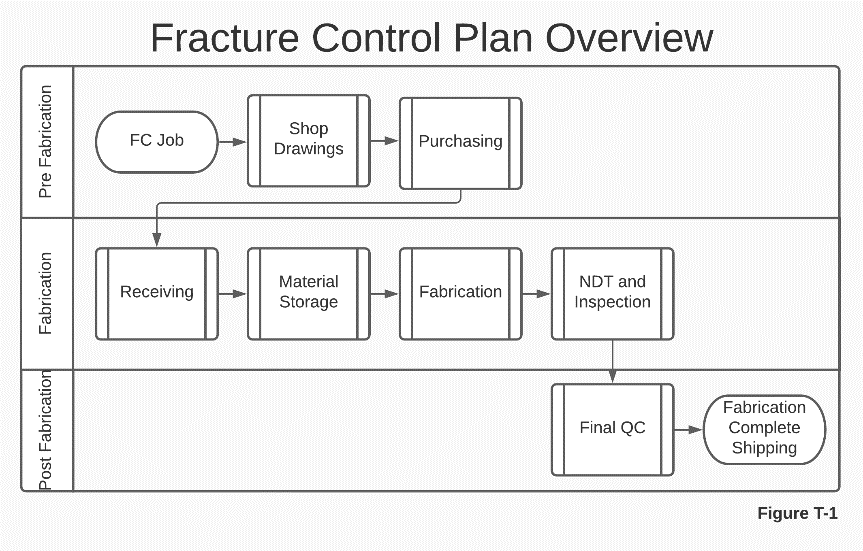
6.2 Shop Drawings
The process of fabricating FCM begins at the shop drawing stage, carries through the material purchasing stage, and affects all shop fabrication related functions in the following manner;
Following the D1.5 FCP ensures that Seacoast uses the appropriate materials and consumables and that welding processes adhere to the more strict standards for the welding of FCM, including, but not limited to provisions for:
- The choice of welding processes per Article 12.5
- Consumable requirements per Article 12.6, including the more strict Diffusible Hydrogen of Weld Metal requirements.
- All WPS per D1.5 FCP 12.7 including preheat and interpass heat per Article 12.14 and post-weld heat treatment per Article 12.15
- Thermal cutting and edge treatment per Article 12.10
- NDT and weld inspection of FCM per Article 12.16.
- Any repairs to materials designated as FCM per Article 12.17
Shop drawings follow all the requirements documented in the QCM Detailing (Section E) of this manual, and for Fracture Critical fabrications have additional provisions per D1.5 FCP:
- Identify Fracture Critical Members per Article 12.2.2
- Identify the appropriate WPS per Article 12.7
- Identify specific testing and inspection requirements per Article 12.16
- Identify any straightening, curving, or cambering required per Article 12.12
- Advance bills of material will have FCM identified, per Article 12.4
During the shop drawing process, the Engineering Department will review all design drawings for members designated as FCM. The Seacoast Engineering department will coordinate, through the detailing and shop drawing submittal process and through the RFI process, where necessary, to confirm materials designated as FC is noted. The Engineering Department will ensure that all shop drawings document FCM, WPS, and NDT requirements per Article 12.3.
6.3 Purchasing
Order materials from the bill of materials or directed by a competent person; the order will include the ASTM specification or the contract specified physical and chemical properties. As necessary, have additional requirements in the material order for:
- Charpy V-notch requirements, with specified temperature zone and method of joining.
- AASHTO Temperature Zone
- Supplemental CVN Test Requirements
- Fine-Grain Practice
- Prohibition of Mill Repairs
- Low-stress dies for markings.
- Note on all documentation that these are materials for use as Fracture Critical Material
As necessary or required by the contract, the material order may include additional material order requirements for the following:
- Carbon Content Minimum/Maximum
- Low-sulfur (0.010%Minimum)
- Improved through-thickness properties (example ASTM A770)
- HT requirement of Normal/Quench and Temper/Other
- Special heat treatment
- Supplemental Specifications
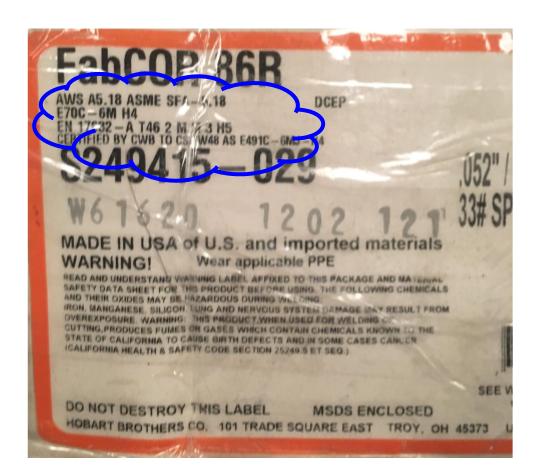
Welding Consumables: Seacoast FC WPS includes consumable information like filler metal AWS Specification, Classification, and a Manufacturer Trade Name. Welding consumables are purchased per the WPS documented on the shop drawings or directed by a competent person. Order consumables that meet the manufacturer's requirements, producing them under a qualified continuing quality assurance program.
Purchasing FCM and consumables per these requirements and follow the procedures documented in QCM Purchasing (Section P) of this manual. Fracture Critical Material has a specific Material Quote (MQFC01) form and Purchase Order (POFC01) form to ensure that FC material is ordered, received, and handled with the care required per D1.5 FCP.
6.4 Receiving and Material Storage
| Step | Description |
|---|---|
| 1 | Seacoast receives an FCM delivery. |
| 2 | Perform a visual inspection for base metal (check for discontinuities per D1.5 FCP-12.9) and weld consumables (verify the package(s) are sealed and undamaged). If the material does not pass visual inspection, Notify the Shop Engineer before accepting delivery |
| 3 | The driver provides a delivery ticket with the material. Match the delivery ticket to the material delivered |
| 4 | Pull the PO from the receiving desk. Compare the PO's material to the delivery ticket, paying particular attention to the type, ASTM, size, and grade (for welding consumable see note below) |
| 5 | Compare the quantity of material from the PO and the delivery ticket. |
| 6 | Staple the PO, delivery ticket, and MTR/certification documents together and put them in the "For Office" bin in the receiving area |
| 7 | Store the material in the assigned "Qualified" material location, documented in QCM Receiving (Section Q) in this manual. |
6.5 Fabrication
| Step | Description |
|---|---|
| 1 | Conduct prefabrication meeting per QCM Fabricator Process Control (Section G) of this manual |
| 2 | Review the certification and qualifications for shop staff assignments per D1.5 FCP 12.8 |
| 3 | Before beginning a process, perform an as-received inspection of base metals. This inspection is in addition to the as-receiving inspection at the time of FCM delivery. |
| 4 | Preparation of material before or post welding per D1.5 FCP |
| 5 | All welding requirements listed within the QCM and D1.5 apply, except as modified herein. Following D1.5 Clause 8, all welds will either be prequalified or follow a WPS with documented qualifying PQR. Welding will follow the requirements for welding. |
| 6 | Perform welding as documented on the drawing using the approved WPS from the drawing |
| 7 | Inspect FC Welds per Inspection of Fracture Critical Welds in this section |
Step 4 — Material Preparation Details:
| Process | Description |
|---|---|
| Thermal Cutting | Materials will be prepared by thermal cutting as required per Article 12.10. Universal milled and sheared plates will be thermal cut to remove a minimum of 3/16" material from the edge. This does not apply to bars and shapes meeting ASTM A6. |
| Repair of Base Metal | Base metal discontinuities adjacent to FC butt joints per Article 12.10.3 will be repaired or replaced in conformance to Article 12.11 |
| Straightening, Curving, and Cambering | Cold bending is prohibited for all FC steels unless approved by the EOR through the RFI process see QCM Document, Data & Quality Record Control (Section F). Otherwise, follow the requirements of Article 12.12 |
Step 5 — Welding Details:
| Process | Description |
|---|---|
| Tack welds and temporary welds | Tack welding of components of members together and completing welds. Tack welding will only be performed as allowed within D1.5 FCP Article 12.13, depending on the process used for producing the tack weld and the process used that will produce the weld that consumes the tacks. All tack welding will be per D1.5 FCP, Table 12.3. |
| Preheating | All preheating required for either the tack welds or the final welds will be performed to meet the requirements of D1.5 FCP. All preheating will be per Tables 12.3 - 12.8 of D1.5 FCP |
| Interpass | Interpass temperatures will be monitored and maintained per Tables 12.3 - 12.8 of D1.5 FCP. |
| Postweld thermal treatment | Postweld thermal treatment will be per the approved WPS and Article 12.15 of D1.5 FCP |
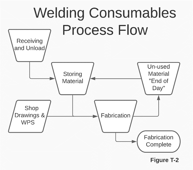
6.6 Welding Consumables
All consumable items will be controlled by order, lot, storage, and use per D1.5 FCP Clause 12. Note these additional considerations
- Match drawing requirements and WPS to Welding Material/Consumable type required
- Pull consumable material and verify size and grade
- Execute fabrication requirements per drawing
- At 'End of Day,' store welding consumables in assigned material 'Oven.'
The Shop Engineer, a CWI, is responsible for overseeing all consumable requirements per 12.6, including but not limited to packaging, storage, drying, drying ovens, atmospheric exposure, and exposure limits for all FC allowable weld processes typically SMAW, GMAW, and SAW at Seacoast.
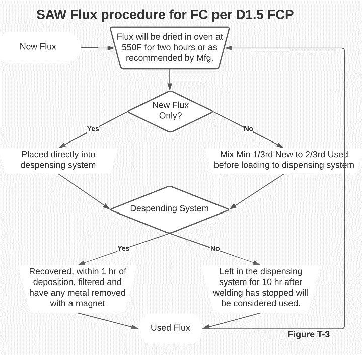
For SAW Flux specifically:
- All new SAW flux will be dried at 550F for two hours before use
- All SAW flux will be discarded after the first use
- Follow all the consumable requirements per Article 12.6 that apply to this process
6.7 Inspection of Fracture Critical Welds
Welding and weld inspection will meet the requirements of D1.5 Clause 8 and will be supplemented by these additional weld inspection requirements per D1.5 FCP Article 12.16 for FCM.
All welds will be allowed to cool for at least the amount of time specified in D1.5 FCP Article 12.16.4 before performing UT, MT, or a final inspection.
| Topic | Description |
|---|---|
| QC | The welding inspector will meet the lead QA and QC requirements: having a minimum of three years' experience in steel bridge fabrication. The lead inspector is responsible for ensuring the welding is per D1.5 FCP, the approved WPS, and any other contract document requirements. |
| NDT Technicians | As per D1.5 FCP Article 12.16.1.2, NDT technicians will be certified to Level II or certified to Level III and qualified to perform as a Level II in conformance with ASNT's Recommended Practice SNT-TC-1A. |
| Type of welds and NDT Required | See table below |
| Record Keeping | Inspection and record-keeping will be as per D1.5 FCP 12.16.5, also see Quality Control Records at the beginning of this section. |
NDT Requirements by Weld Type:
| Weld Type | NDT Required |
|---|---|
| Tension Welds or Repaired Welds in Butt Joints | Both RT and UT |
| T and Corner Joint Tension Welds and Repaired Groove Welds | UT |
| Fillet Welds | MT |
| Fillet Weld Repairs | MT 100% of Length of Repair |
6.8 Non-conforming Product (Repair Welding)
Weld repairs are defined as any welding, including removal of weld or base metal in preparation for welding, necessary to correct unacceptable discontinuities in materials or workmanship. Weld repairs will be classified as critical and non-critical per the definitions of D1.5 FCP
| Type | Description |
|---|---|
| Non-critical | Non-critical repair welds are generally welds to deposit additional weld beads or layers to compensate for insufficient weld size and to fill limited excavations to remove unacceptable edge or surface discontinuities, rollover, or undercut. Non-critical discontinuities are as defined in Article 12.17.2 of D1.5 FCP. Non-critical repairs will follow the applicable approved WPS. |
| Critical | Critical repair welds are any weld repairs to FCM that are not excluded as being non-critical in the definition above. Refer to Article 12.17.3 for most examples. All critical repairs will be discussed with the Engineer of Record (EOR) and any third-party welding specialist or inspector and will not start until approved by the EOR and in-house parties. A WPS related specifically to the type of repair to be performed will be generated, approved, and followed. The WPS will include all applicable requirements of Article 12.17.6 of D1.5 FCP. Welding and inspection will adhere to the approved WPS for the weld procedure. All critical repairs will be documented and WPS submitted to the EOR per a Request for Information (RFI). Repair welding will not begin until EOR approval is established as part of the RFI process; see QCM Document, Data & Quality Record Control (Section F) of this manual. |
7. Revision History
| Revision Date | Approved By |
|---|---|
| 2026-05-12 | Shop Engineer |
Summary of Change: Reformatted to standard procedure template.