G. Fabricator Process Control
1. Purpose
To establish documented procedures that ensure a controlled process consistently producing an acceptable level of quality in the finished product per customer contract requirements and applicable specifications and standards.
2. Definitions
For readability, this section uses the following abbreviations and terms.
- 2.1 Final Inspection: The comprehensive examination of a completed product or component to ensure it meets all specified standards, requirements, and quality criteria before it is approved for delivery or release.
- 2.2 Heat Number (HT#): The Heat Number (HT#) is a unique identifier assigned to a batch of metal during its production, typically during the melting process. It tracks the specific batch of material used in manufacturing, allowing traceability to the raw material's origin, chemical composition, and processing history. The Mill Test Report includes the HT#.
- 2.3 Hold Point: A hold point is a predefined stage where work is paused for inspection or approval, ensuring quality and compliance before proceeding.
- 2.4 In-Process Inspection: The examination and verification of products or components during the manufacturing process to ensure they meet specified standards and requirements before continuing to the next stage of production.
- 2.5 Mill Test Report (MTR): A Mill Test Report (MTR) is a quality assurance document that certifies a metal product's chemical and physical properties. It provides detailed information about the material's composition, mechanical properties, heat treatment, and compliance with industry standards per ASTM A6, verifying that the metal meets specified requirements for use in fabrication or construction.
3. References
The following references directly support this section:
- 3.1 AASHTO/NSBA G4.1 Steel Bridge Fabrication QC/QA Guidelines (informative reference)
- 3.2 Single Point Lesson, SPL-002 Fab Piece Markings
- 3.3 Single Point Lesson, SPL-009 Burn Table Hole Making
- 3.4 Single Point Lesson, SPL-010 Burn Table Plate Nest
- 3.5 Single Point Lesson, SPL-011 Final Inspection Mark
- 3.6 Single Point Lesson, SPL-012 Approved Cut List
4. Responsibilities
- 4.1 Owner of Process: The Shop Engineer is responsible for reviewing and approving this section. Final approval is the responsibility of the Quality Control Manager.
- 4.2 Shop Engineer: The Shop Engineer collaborates with the Shop Foreman to develop a fabrication plan, ensuring compliance with contract requirements and quality standards. If applicable, review and understand the shop assembly procedures. Monitor quality control processes to ensure meeting all requirements throughout the fabrication project.
- 4.3 Quality Control Inspector (QCI): Perform inspections, tests, and measurements at various stages of production to identify defects or deviations, ensuring that the final product is of the required quality before approval for release.
- 4.4 Shop Foreman: Oversees the fabrication process to ensure it aligns with the fabrication plan. Manages day-to-day operations in the shop to maintain safety, efficiency, and quality.
- 4.5 Competent Person: An individual with the necessary skills, knowledge, experience, and qualifications to perform specific tasks or inspections ensures that work meets established standards and safety requirements.
5. Quality Records
Unless otherwise noted, all Quality Records follow the Seacoast "Policy for Maintenance of Quality Records" documented in the QCM Quality Control Plan Article 9. Control of Quality Records.
- 5.1 Burn Table Plate Nest: It is stored in the Seacoast Reference Library after the part is produced. After fabrication is completed, it is stored in the Seacoast Reference Library filing cabinet.
- 5.2 Cut List: It is stored in the Shop Filing Cabinet for use during fabrication. When the job is retired, it is held in the Seacoast Reference Library and ultimately digitally stored under the job. \\siserver\Jobs\Old Jobs[JOB] Transmittals_RFI_RFM_Submittals\Shop Released.
- 5.3 Quality Control Drawing set with the inspection result: Stored in the Shop Engineers' office for use during fabrication. When the job is retired, it is held in the Seacoast Reference Library and ultimately digitally stored under the job. \\siserver\Jobs\Old Jobs[JOB] Transmittals_RFI_RFM_Submittals\Shop Released.
6. Documentation
6.1 Process Control Overview
Fabrication is dependent on customer-approved drawings. Figure G-1 represents an overview of the drawing approval process, resulting in the release for construction drawings used for fabricating.
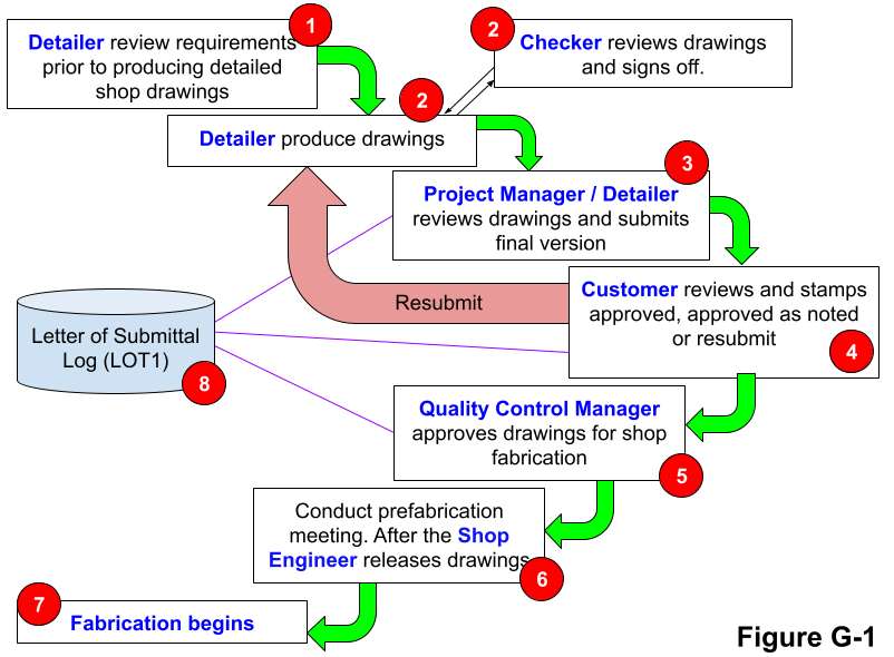
Figure G-1. Process Control Overview
For a comprehensive understanding of the steps documented in Figure G-1. The item numbers below map to Figure G-1. Refer to the sections listed for specific details.
| Item | Description |
|---|---|
| 1 | See "Contract and Specification Review" Section D |
| 2-5 | See "Detailing" Section E |
| 6 | See "Shop Pre-Fabrication Meeting" in this section |
| 7 | See "Shop Process Control" in this section |
| 8 | See the "Document, Data & Quality Control Records" Section F |
6.2 Shop Pre-Fabrication Meeting
Seacoast has invested considerable effort in planning the project and developing the drawings. Seacoast is confident that the final product will meet customer requirements, having received answers to all inquiries and customer approval of the drawings. With these approvals in place, fabrication begins with the shop pre-fabrication meeting.
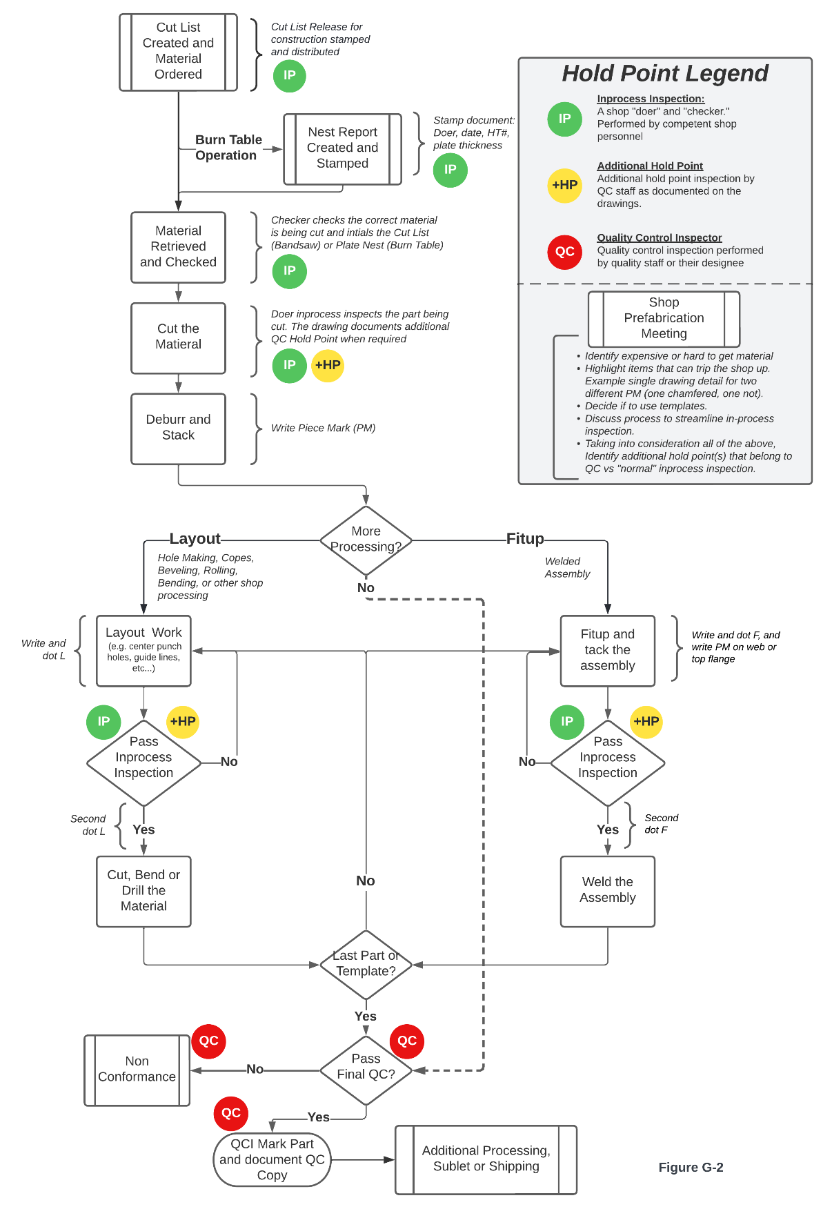
Figure G-2. Fabrication Process Control
Figure G-2 documents the key steps in the fabrication process control and includes inspection hold points up to and including the final inspection.
| Step | Description |
|---|---|
| 1 | The owner approves the release for construction drawings, and the drawings are logged, stamped, and distributed. See the "Detailing" Section E for specific procedures. |
| 2 | Fabrication deadlines assigned. The shop foreman confirms material availability and coordinates the delivery schedule with the purchaser. The project manager (or field engineer), shop engineer, and shop foreman coordinate the current workload, shop capacity, and project deadlines to set a fabrication deadline. |
| 3 | The shop engineer, QCI, and shop foreman independently review the drawings. The shop foreman identifies the staff, processes, and equipment necessary to produce the finished product. The shop engineer reviews for fracture critical material, welding, NDT, distortion control, and other engineering considerations. The QCI reviews for quality control sampling needs and non-typical measurement tool requirements. |
| 4 | The pre-fabrication meeting takes place, and anything out-of-the-ordinary is discussed. |
| 5 | After the pre-fabrication meeting: Distribute release for construction drawings. Document due dates on the shop board. The shop foreman assigns shop staff to production. |
| 6 | Fabrication begins. |
6.3 Process Control Documentation
Many of the process control topics require their own section for readability. The table below lists fabrication processes with additional documentation references to comprehensively understand fabrication process controls.
| Item | Process | Location of Documentation |
|---|---|---|
| 1 | Band Saw | See "Band Saw Process Control" in this section and Single Point Lessons: SPL-002, Fab Piece Markings. SPL-012, Approved Cut List |
| 2 | Bolting | See "Bolt Installation/Rivet Removal" Section J. |
| 3 | Burn Table | See "Burn Table Process Control" in this section and also Single Point Lessons: SPL-002, Fab Piece Markings. SPL-009, Burn Table Hole Making. SPL-010, Burn Table Plate Nest |
| 4 | Cambering | See "Cambering" Section I. |
| 5 | Distortion Control | See "Distortion Control Program" Section V. |
| 6 | Equipment Maintenance | See "Equipment Maintenance" Section C. |
| 7 | Fracture Control | See "Fracture Control Procedure" Section T. |
| 8 | Inspection | See "Inspection and Testing" Section L and Single Point Lesson SPL-011, Final Inspection Mark. |
| 9 | Match Marking | See "Match Marking" Section U. |
| 10 | Painting | See "Painting" Section K. |
| 11 | Shop Assembly | See "Shop Assembly" Section X. |
| 12 | Welding | See "Welding Process" Section H. |
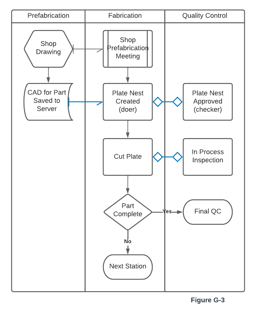
6.4 Burn Table Process Control
To produce quality parts and minimize waste from non-conforming parts, follow the steps below when operating the burn table.
| Step | Description |
|---|---|
| 1 | After the shop pre-fabrication meeting, the burn table operator is notified the job is starting. |
| 2 | The burn table operator retrieves the released for construction drawing set from the shop filing cabinet. |
| 3 | Retrieve the CAD (.dwg) file from the shared server. If the file isn't available, contact the drawing detailer and notify them that it is required, or inform the shop engineer of the missing file. |
| 4 | Create a plate nest using the CAD file from the previous step. Nest all parts with the same thickness and specification that fit on the plate. |
| 5 | When the nest is complete, print the Hypertherm Report, stamp it, document the Heat Number (HT#) and plate thickness, and provide it to a competent person (checker) for review. |
| 6 | The competent person (checker) reviews the plate nest for correct plate thickness, part count(s), efficient nest, plate grade, and heat number from the mill test report (see single point lesson SPL-010 Plate Nest Approval). |
| 7 | Load the plate to the table (doer) and have a competent person (checker) other than the person who retrieved the plate check the plate thickness using a tape measure. |
| 8 | Cut the first part, and check the part's dimensions. If the part includes table cut holes in-process, inspect the quality of the holes (see single point lesson SPL-009 Burn Table Hole Making) |
| 9 | Once the entire plate is processed. Piece mark each piece according to the fabrication piece marking process (see single point lesson SPL-002 Fab Piece Marking) |
| 10 | Once the plate is processed, clean up the parts and move them to the next step in fabrication or final inspection. |
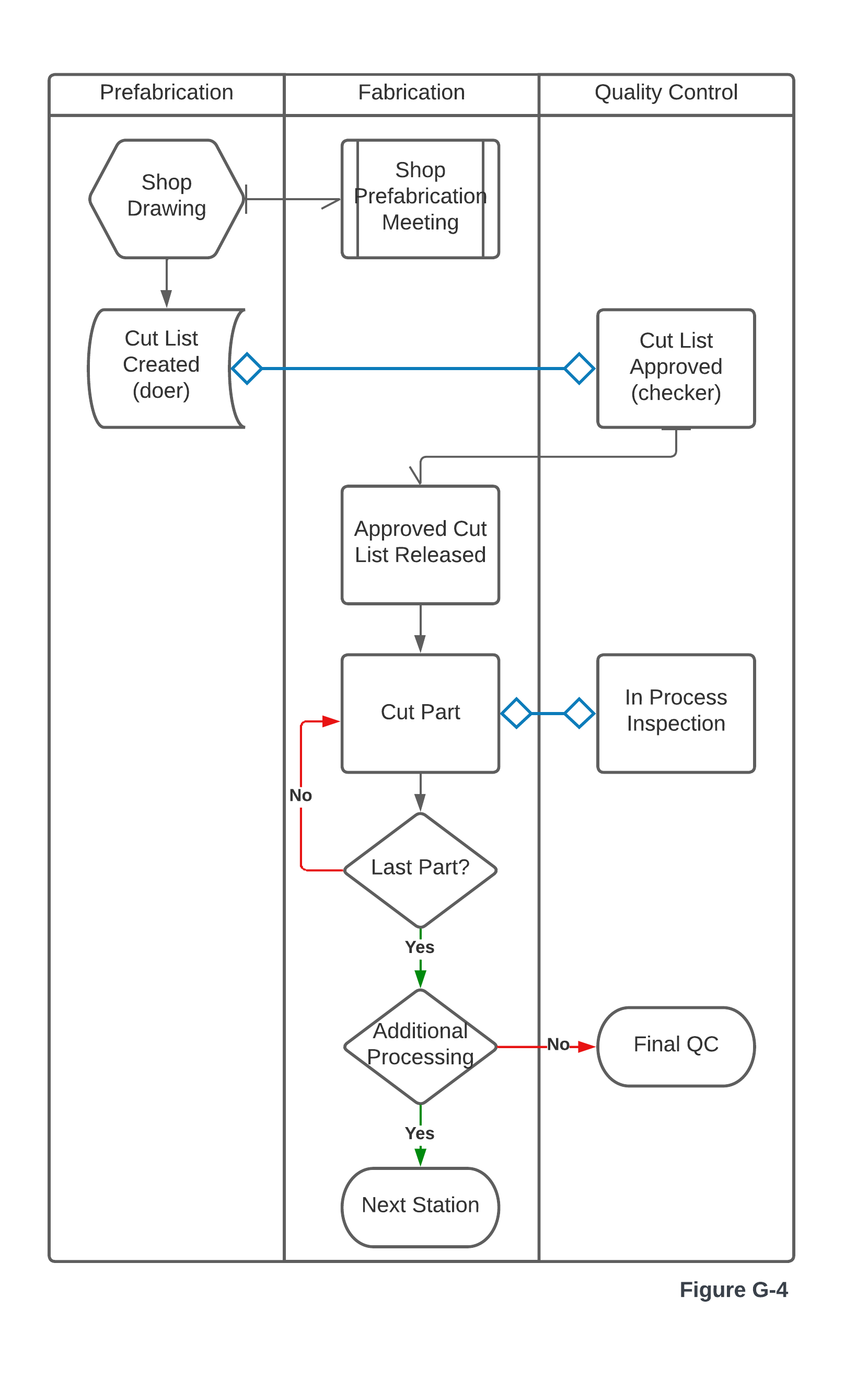
6.5 Band Saw Process Control
To produce quality parts and minimize waste from non-conforming parts, follow the steps below when operating the band saw.
| Step | Description |
|---|---|
| 1 | After the shop pre-fabrication meeting, the band saw operator is notified the job is starting. |
| 2 | A competent person (doer) creates a Cut List per the Bill of Material (BOM) for the released for construction drawing (see single point lesson SPL-012 Approved Cut List). |
| 3 | A competent person (checker) reviews the Cut List for accuracy. |
| 4 | The Band Saw Operator retrieves the drawing and approved cut list in preparation for cutting parts. |
| 5 | Load the material to the band saw feed table (doer) and have a competent person (checker) other than the person who retrieved the material check the material dimensions using a tape measure. |
| 6 | Per the Cut List, cut until all parts are completed, and in process inspect each part. |
| 7 | Once the unique row of material from the cut list is processed piece mark each part according to the fabrication piece marking process (see single point lesson SPL-002 Fab Piece Marking) |
| 8 | Clean up the part once the entire quantity of a piece mark is processed. Inform the shop foreman the part is ready for the next step in fabrication or final inspection. |
7. Revision History
| Revision Date | Approved By |
|---|---|
| 2026-05-12 | Shop Engineer |
Summary of Change: Reformatted to standard procedure template.